
But how?
So in the last post we covered why I’m building a CNC needle cutter. In this one, we’ll look at how I plan to do that.
DISCLAIMER: I’d like to take a moment to remind you- the reader- that this is a build log and NOT a construction manual. I’m learning as I go and everything is subject to change, so keep that in mind.
Anyway, moving on!
Let’s start with a loose parts list. I’m leaving out all of the individual nuts and bolts here cause those are changing all the time. I’ll just show what I know:
- M3 nuts and bolts
- M5 bolts and T-nuts
- 1000mm V-slot extrusion
- 600mm V-slot extrusion
- V-Slot wheels
- A few meters of GT2 belt
- GT2 pulleys and idlers
- Some metal tube to crimp on the belt ends
- Lots of 3D printed parts
- Three NEMA 17 stepper motors
- One lil stubby NEMA 17 motor
- Printrboard Rev. D
Those last few are on the list because I’m harvesting the kinematic components from a Printrbot Simple. This little printer will live another life yet (although I also grabbed an $8.00 Ramps 1.4 board, just in case).
I’ll be running grbl firmware with UGS platform by the end if all goes well. If you don’t think the Printrboard is compatible with grbl, prepare to be surprised! A fellow maker by the name of Lincomatic posted some ported firmware on his blog back in 2012. Yes, I intend to base my entire control system on one-person-ported firmware from seven years ago. Wish me luck!
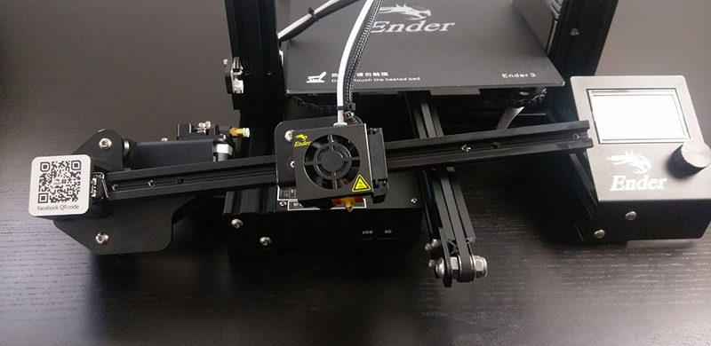
Back on the physical side of things, we’re looking at a pretty standard box construction with the “endmill” moving along an X axis rail, which itself uses two driven carriages to move along a pair of Y axis rails.
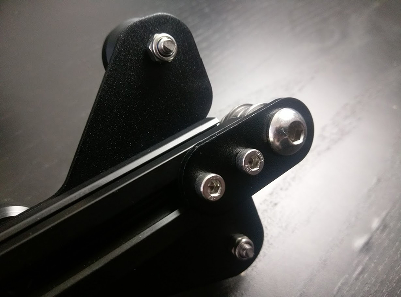
The movement will be pretty similar to parts of an Ender 3, with a motor and tensioner pulley at opposite ends of a rail (with a belt running inside the 2020’s grooves, which allows the carriage to seamlessly roll over it the belt without). Both ends of the belt are fastened to the carriage on the bottom, closing the loop.
Here’s a diagram illustrating the motor and axis layout:
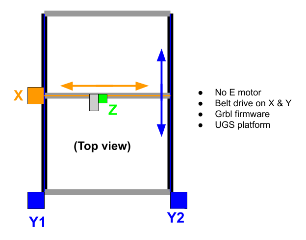
For the two Y axis motors, nobody seems to care about cloning motor signal to another output on this board, so they just use one of these motor splitter cables:

So yeah, that’s my master plan.
The next post should be construction update. Y’know, the juicy stuff 😉