
Cutter head intermission
Hey guys,
This post is an in-depth look at the evolution of the needle cutter head & Z carriage, and the relentless troubleshooting that went with it
It’s been a while but I’m back. Progress has been slow, in part due to my undeniable laziness, but we’re back up and running (kinda) again! Let’s go back to the beginning of the conundrum.
v1.0/v1.1
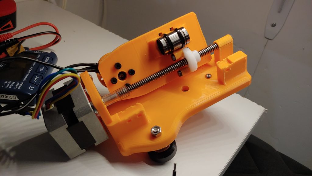
This is where the trouble began. My first Z axis and cutter design. It has a linear bearing running on a steel linear rod, and a simple rubber tube coupling that fastened the motor shaft to a lead screw. It may not look too dastardly at first, but ooohhh just you wait.
What’s wrong with it, you ask? Well let’s start at the lead screw, or more specifically, the T-nut that an on it. Harvested from a Printrbot Simple (the classic wood kind), the slop in that nut, even from the one side was enough to create horribly wobbly line. Another issue was the frankly irresponsible lead screw guide at the bottom of v1.0. It was already cracked within 10 minutes of installation, and for some reason I thought that the single rubber coupler could keep it from wobbling. Went well right? Yeah not so much.
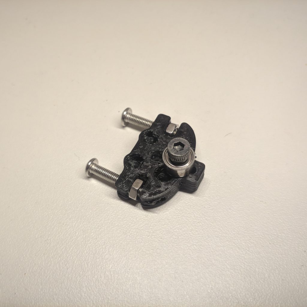
The Coupling Problem:
I also had a major issue with the coupling. I started out with a basic rubber(?) tube with either side clamped on to the motor shaft and lead screw respectively, but this didn’t work for a number of reasons. At this point I should point out that it had absolutely no problem with rotational slippage, it only failed when it was outside of its intended use case. On the PB Simple, this coupling was not a problem because the motor was on the bottom, supporting the load of the Z carriage on the lead screw which was resting on the shaft, thus it was pressed together constantly. This method only became an issue when the mechanism was flipped upside down, because the coupling was now having to keep the lead screw from slipping off of the motor shaft, something it was not at all intended for.
“Why not just use a proper metal coupling or strong zip ties” you ask? To put it simply; space. The tolerences were so tight in this early design that even the nubs of zip ties would get stuck against the back of the carriage. My final attempt before reprinting was a spring hose clamp with the tabs ground off (visible below a ways). This still slipped off, and I was forced to admit defeat and reprint the part with space for a proper coupling, which fixed the problem immediately.
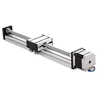
On v1.1 I added a 608 bearing, and shortly after that I swapped out the lead screw for a higher pitch acme screw with a brass T-nut:
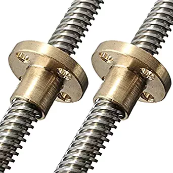
That definitely helped a little, but not nearly enough to to eliminate all of the wobble, and I eventually decided I had no choice but to switch to a dual rod design.
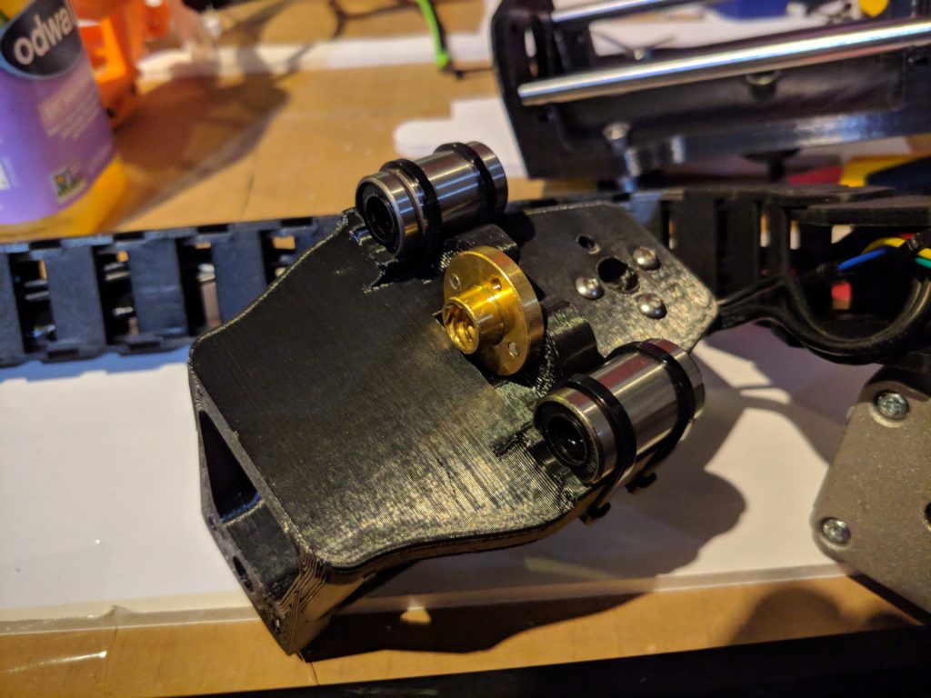
Ok, dual rod design. It goes like this:
1. Center the Z screw and motor.
2. Double up on the steel rod and add another bearing to go with it.
3. Keep the bearing at the bottom, make sure the new design isn’t any wider than the last one.
That last point was pretty important– the width I mean. With the 600mm beams I had ordered for the X axis, the framework ended up chopping off a couple centimeters, which meant that my working area had been reduced to 18< inches wide, which then meant I could not make use of the whole 20-inch wide foam board piece like I had intended, and also meant that from here on out I am extremely protective of my X travel.

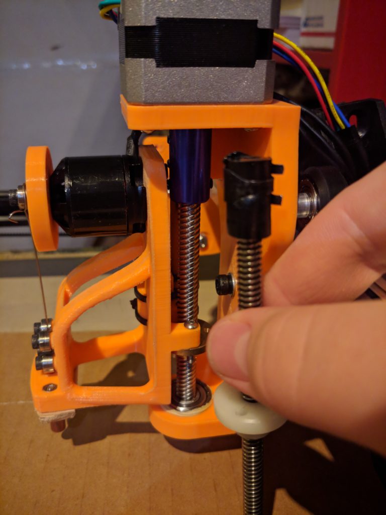
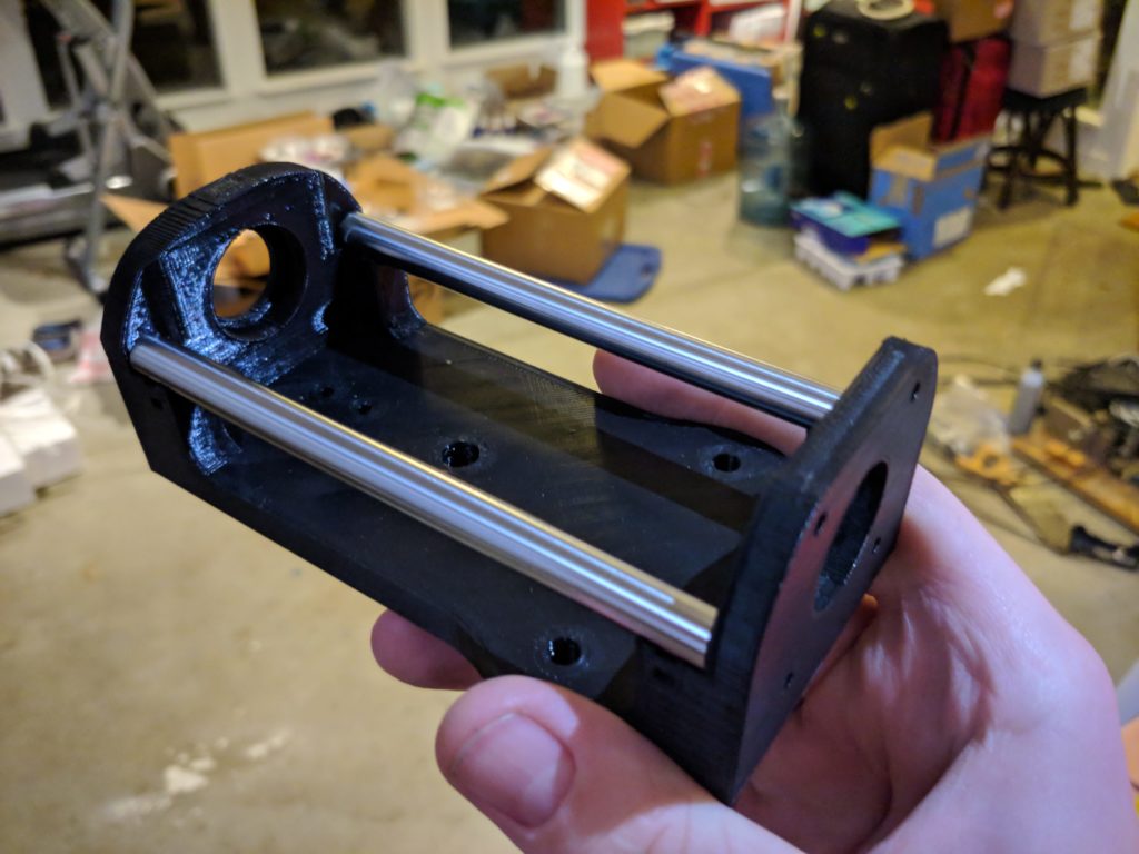
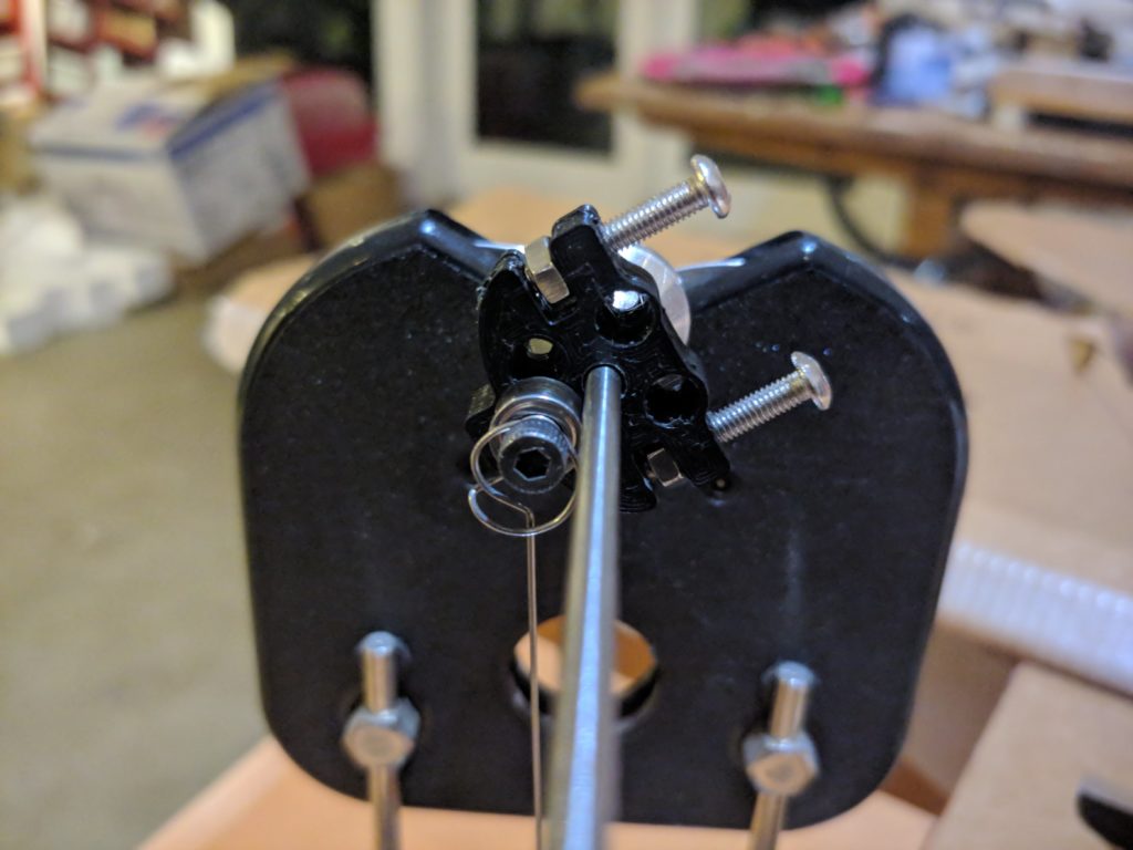
So here’s the basis of our dual rod carriage design:
This design definitely improved the amount of slop, reducing it to almost zero, and it’s actually narrowe than the single rod design! At this point the only slop comes from the X carriage, which is another issues entirely.
The Mystery of Z Inconsistency
Let’s take a look at another area in need of improvement: the tool itself. Starting with the Z movement (that fits in the toolhead category, right? Screw it, my blog my titles), I was experiencing an issue where the Z axis seemed to be all over the place, and it would always return below where I had homed it before the cut. I checked the coupler, which hadn’t slipped, I check the GCode, which was (probably) sound. After lots of thinking and swearing and giving up and checking the prices of premade CNC machines, I finally found the issues, and it was a strange combination of hardware, software, and operator error.
Here’s what was happening: I would home the Z axis, then turn on the brushless cutter motor, and start the cut. After that the machine would confidently ram the tip right into the material as I yelled. As it turns out, after I had finished homing Z, the stepper motor drivers would turn off and relax the motors. This meant that in combination with the higher pitch acme screw, the vibrations from the cutter motor would slowly move the Z axis down before the print started and the motor drivers had reinitialized
Slop Hunt!
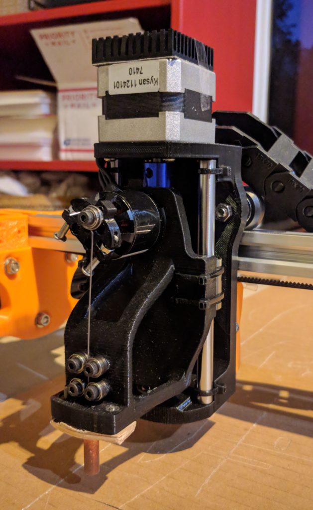
Alrighty, I’ve tracked down and squashed a few sources of slop such as the Z coupler/shaft, the Z carriage, and a couple others, but the big soft elephant in the room in still sitting there: wheels. There are plenty of reasons CNC machines use beefy rails instead of a set of plastic wheels, and one of those is rigidity.
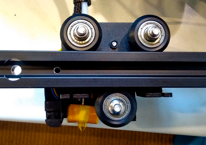
This wheel system works fine for the Y axis, but at the moment we have lots of hardware– including two motors and several steels rods– hanging off the side of this mechanism. Unfortunately this is pretty far outside of the carriage’s limits and it’s showing some serious droop. Hey, I would too.
Solutions!
Should I drop $2,000 on a giant linear rail? Replace the whole thing with rods? There are so many ways to do it. At the moment I’m toying with the idea of using the one leftover 600mm extrusion on the other side of the cutter head to brace it. Or I could use a linear rod.
I could also try moving the motor to the other side and using a small belt loop to drive the Z axis, using the motor as a counterweight. Another solution is to flip the motor upside down and hang it under the beam, creating a U-shape to move the center of gravity closer.
However, at the moment I can simply live with it.
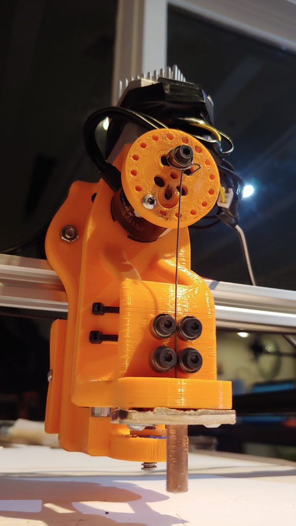
The New Flywheel
Finally, we can focus on a smaller detail– literally. This new design for a flywheel is based on variable centrifugal force, and significantly cuts down on vibration. Here’s a picture:
Congrats, you’ve managed to read and/or scroll through 52 pages of boring blither and me complaining! As a reward, have a picture of the (hopefully) finished an final design:
As much as I would like to continue rambling, it is now 5 A.M. and I have lots of other responsibilities to ignore. Also I didn’t proofread this.
—-> concentric spacer that clamps it up to the rail…
eccentric spacer?
Ah, right. Took so long to teach myself to call it a “concentric spacer” and now I wake up and it’s the other way around. Let’s just blame it on the Mandela effect or something 😉